7058 4-Channel Vibration Monitor
Four channels of digitally accurate vibration protection with a single versatile instrument
The 7058 4-Channel Vibration Monitor measures the vibration level of one to four points on rotating equipment located up to 1,000 feet from your central control room, ideally suited for monitoring multiple points on large equipment like turbines and multi-stage pumps. Can be configured to: (1) accept signals from acceleration transducers, velocity transducers or non-contact probes; (2) condition signals to monitor in acceleration (g’s), velocity (in/sec) or displacement (mils); and (3) low-pass, bandpass and high-pass filters for each channel to allow you to monitor for a particular problem or to remove unwanted signals generated by nearby machines.
A single analog meter allows you to view the vibration level, alarm and trip setpoint for each channel, and can be set to display the highest vibration level of the four channels. Front panel LEDs give immediate indication when alarm and trip setpoints have been exceeded, or when power or a transducer signal has been lost. AC and DC signal outputs and multiple relays allow for connection to external devices for alarm or automatic shutdown.
Download Product Literature
Transducer Input |
Accelerometer |
Ranges |
Various |
Measurement Mode |
Acceleration, g’s (Acceleration input only) |
Relay |
One common alarm relay for all channels |
Relay Contact Ratings |
5A @ 120V AC, 2A @ 28V DC non-inductive, epoxy sealed. |
Relay State |
Alarm, trip and probe fault relays are latching and normally de – energized below setpoint (standard) |
Limit |
Independently adjustable alarm and trip setpoint for each channel, 0 – 100% full scale. |
Time Delay |
One-second fixed alarm and trip delay, up to 10 seconds on special order. |
Start-up Attenuation |
Remote contact closure by user provides start-up attenuation of 3:1 for all channels. |
Operating Temperature Range°F |
+32 to +130F (0 to +54C), 0 – 95% relative humidity non-condensing. |
Meter Accuracy |
± 2% |
Input Power |
115V AC, 50/60 Hz (Standard) |
Limit Designations |
Green LED for power on. |
Output (AC) |
Front panel BNC jack provides AC signal for analysis, proportional to transducer input for selected channel. |
Analog Output |
0-1V, 0-5V or 4-20mA DC |
Optional Accessories |
(412554-258) 30-second start up time delay (79904-137A) Dust and Liquid Tight Cover |
|
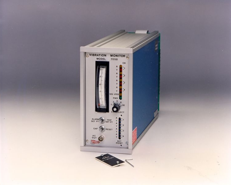
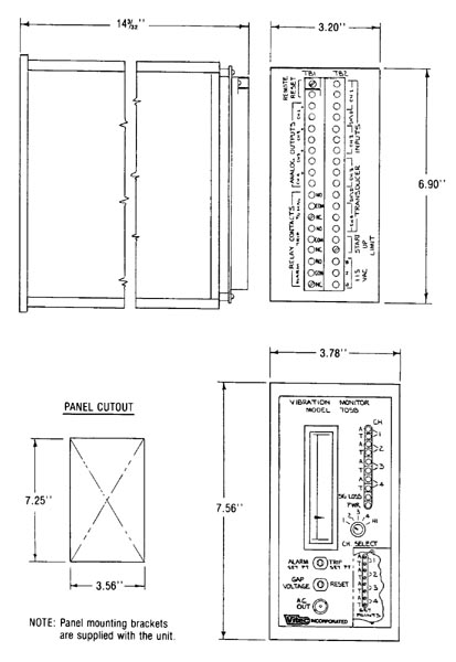
The Vitec Model 7058 Vibration Monitor provides a low-cost, compact, panel-mounted monitoring package for up to four channels of continuous vibration protection. Ideal for OEMs and end users alike, this unit accepts inputs from accelerometers, velocity transducers, or non-contact probes. The 7058 was designed specifically to provide low-cost monitoring protection for applications where one channel of protection is not enough, and a large complicated system is too much. The Vitec Model 7058 Vibration Monitor is completely self-contained. It includes the power supply, meter readout, power and transducer malfunction LEDs, and an individually adjustable alarm and trip setpoint with corresponding alarm and trip LED for each of its four channels. By using concepts from Vitec high-density monitoring systems, all this is accomplished in less than 29 square inches of panel space. |
The monitor front panel contains a vertical scale meter which indicates the individual channel vibration levels, as well as the alarm and trip setpoints. A vertical row of LEDs indicates when any of the four channels has exceeded its alarm or trip setpoints (yellow for alarm, red for trip). A yellow signal loss LED is illuminated upon loss of a vibration signal from any of the four transducers. A green “Power On” LED indicates that power is supplied to the monitor. The indicating LEDs and the common alarm, trip and signal loss relays are latching. The channel select switch allows a readout of any of the four channels, or on the “HI” position, the meter will automatically read out the highest of the four inputs. Beneath the meter is a switch labeled “Alarm Setpoint” and “Trip Setpoint” The alarm position allows a readout of the alarm setpoint on the vertical meter for the selected channel; the trip position allows a readout of the trip setpoint. Another switch below this one allows relays to be reset or indicates a readout of the probe standoff if a non-contact type probe is being used. The “AC OUT” jack on the front panel provides a buffered AC signal proportional to the vibration for any of the four selected channels for analysis purposes. |
|
|
Eight relays (optional) for use to indicate:
|