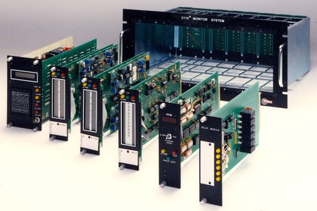
2110 Monitoring System
Measures vibration, speed, temperature and other process variables in any combination
The 2110 provides around-the-clock monitoring of machinery and processing equipment and warns operating personnel when predetermined limits have been exceeded. Individual bar graph displays give continuous indications of each channel, allowing the operator to view vibration, speed or other process variable levels at a glance. LEDs on the individual modules energize to indicate alarm, trip and pick-up status.
The unit features high-density operation, up to 248 channels of process variable monitoring. Modular construction ensures economical system expansion, without the need for field programming or returning the system to the factory for modification. The system combines the proven reliability of analog signal conditioning with the ease of use and dynamic display capabilities of a microprocessor-based system.
The 2110 comes with another valuable feature – Vitec applications support. Our experienced Application Engineers are available to help you custom tailor a system to fit your individual needs or simply answer your vibration questions. A system is only as good as the company that backs it.
Each 2110 Monitoring System is custom-configured to meet the Customer’s exact requirements. Please contact Vitec to have one of our Application Engineers help configure your system and supply a quotation.
Download Product Literature
Input |
Axial position (noncontact probes) |
Modes |
Acceleration (g or m/sec2) |
Ranges |
0.0 to higher number, e.g., to 1.0, to 9,000 |
Filtering |
Bandpass |
Module Sizes |
Control Module: 4″ x 6-7/8″ |
Frequency Response |
4033-400 & 4033-500 Velocity Transducer input: 4034 Velocity Transducer input: 4060 Acceleration Transducer input: 1.0 to 1,500 Hz ±5% 4063 or 4064 Acceleration Transducer input: 4071 Acceleration Transducer input: 4073 Acceleration Transducer input: Non-Contact Probe input: DC to 10,000 Hz ±5% |
Repeatiblity |
±2% |
Operating Temperature Range |
2110 Electronics: +32 to +122F (0 to +50C) 4033-400 Velocity Transducer: -20 to +400F (-29 to +204C) 4033-500 Velocity Transducer: -20 to +500F (-29 to 260C) 4034 Velocity Transducer: -30 to +160F (-34 to +71C) 4060 Acceleration Transducer: -100 to +400F (-73 to +204C) 4063/4064 Acceleration Transducer: -100 to 550F (-73 to +204C) 4071 Acceleration Transducer: -58 to +180F (-50 to +82C) 4073 Acceleration Transducer: -65 to +250F (-54 to +121C) |
Relay Quantity |
Two, standard: Power Loss and Transducer Malfunction |
Number of Relay Setpoints |
One Alarm and one Trip setpoint per input channel |
Function of Relay Setpoints |
Alarm and Trip, both field adjustable |
Range of Setpoint Limits |
0 to 100% of full scale |
Relay Configuration |
Power Loss: Normally Energized Transducer Malfunction: Normally Energized or Normally De-energized (customer-specified), and Non-latching Optional Relay Modules: Normally Energized or De-energized, Latching or Non-latching, customer-specified |
Start-up Limit |
2x multiplication of alarm and trip setpoints |
Relay Time Delay |
1 to 15 seconds, individually adjustable per relay |
Relay Inhibit |
Individual Inhibit switch for each relay in the Relay Module |
First Out |
Indicates first channel to exceed Trip setpoint when multiple channels have exceeded their limits |
System Interrogation |
Keypad allows access to parameters for each channel including monitor point ID, digital display of measured value, alarm and trip limits, System Reset and First Out Reset |
Size |
19″W x 8.75″H x 14″D (48.3 x 22.2 x 35.5cm) |
Weight |
15 to 25 lbs (6.8 to 11.3kg) per rack, depending on number and type of modules |
Mounting |
Mounting: 17.22″ x 8.06″ (43.7 x 20.5cm) panel cutout, 18.16″ x 5.75″(46.1 x 14.6cm) bolt pattern |
Environmental Rating |
Standard: NEMA 1 |
Calibration Requirements |
None |
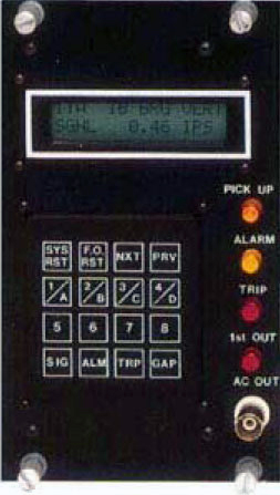
Control Module / Power Supply Front Panel |
16 x 2 character backlit LCD, 16-button lexan keypad. Orange LED for transducer malfunction, yellow for alarm, red for trip and first out. BNC connector for AC signal output. Four knurled and slotted screws for module mounting |
Universal Module (Signal Conditioning) Front Panel |
Four 50-segment LCD bargraphs with blinking segments for alarm and trip setpoint levels, and indications for OK (transducer malfunction), A (Alarm) and T (Trip) for each channel. Yellow LED for alarm, red for trip, green for OK. Eight 20-turn potentiometers (setpoint adjustments). |
Speed Module Front Panel |
4-digit LED display, toggle switch for selecting alarm, trip or running speed. Yellow LED for alarm, red for trip, green for phase lock. Two knurled and slotted screws for module mounting |
Relay Module Front Panel |
Six 20-turn potentiometers for time delay adjustment, 6 DIP switches for relay inhibit. Two knurled and slotted screws for module mounting |
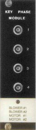
Key Phase Module Front Panel |
Four BNC connectors, engraved panel for BNC designations. Two knurled and slotted screws for module mounting |
System Rack Rear Panel |
Terminal blocks for connection of power, input and output signals. |
2110 Material |
Epoxy coated aluminum front panels; zinc plated steel rack, G-10 epoglass and copper PC boards; metal and plastic switches, connectors and terminal blocks |
Transducer Material |
4034, 4033-400 and 4033-500 Velocity Transducers: anodized aluminum 4060, 4063, 4064, 4071 and 4073 Acceleration Transducers and Non-contact Probes: stainless steel |
Supply Voltage |
120/240V 50/60 Hz AC, or 105 to 150V DC |
Relay Type and Rating |
Dry contact SPDT, 5A @ 150V DC non-inductive |
Transducer Input |
4033-400, 4033-500 Velocity Transducers: 200mV/in/sec pk 4034 Velocity Transducer: 4060, 4063, 4064 Acceleration Transducers: 4071, 4073 Acceleration Transducers: 100 mV/g pk Non-contact probes: |
Analog Output |
0 – 5V DC or 4 – 20 mA DC |
AC Signal Output |
Acceleration Transducer input: 100 mV/g pk Velocity Transducer input: 100 mV/in/sec pk Non-contact probe input: 200 mV/mil pk |
|
The first rack in each system is referred to as the “Master” rack, as it will typically house the control module/power supply and up to six additional monitoring modules. Additional mounting racks are referred to as Slave racks, and are capable of housing up to eight monitoring modules or specialty modules, in any combination. |

|
The 2110 Control Module/Power Supply is a double-wide module located in the first two positions in the Master rack. This module is capable of operating up to 248 channels of continuous monitoring. The keypad allows for system interrogation, providing such features as monitor point ID and digital display of measured values. |
|
High-Density Monitoring Modules In addition to displaying the level of the measured channel, the bargraph display indicates the alarm and trip setpoint for each of the channels with blinking segments in the bar graph. Monitoring points which require four setpoints use two module channels per individual input. In general, there are five different types of signal conditioning modules. Type 53265-2 modules monitor four separate transducers, with one positive Alarm and one positive Trip setpoint per transducer. Type 56265-3 modules monitor two separate transducers with one positive and one negative Alarm and Trip setpoint per transducer. Type 53265-5 modules have the same setpoint configuration as the 53265-3 modules, but utilize a dual-voting system for each point of monitoring. Type 53265-6 modules have channels A & B configured per Type 53265-2 and channels C & D configured per Type 53262-3. Type 53265-7 modules monitor four separate transducers with one negative Alarm and one positive Trip setpoint per channel. Other modules can be custom tailored to specific application requirements |

|
Digital Speed Module Input: Non-Contact Probe Analog Output: 0-5V (standard) or 4-20mA DC (optional) General: The Digital Speed Module provides a single channel of speed monitoring. Digital circuitry is used to allow monitoring accuracies of ± 1 RPM. Display: A digital display provides a continuous indication of speed in RPM. Setpoints: Two individually adjustable setpoints are available for alarm and trip purposes. Moving the toggle switch to the alarm or trip position displays the alarm or trip setpoint on the digital display. Module size: 2″ wide x 6-7/8″ high, uses one module space. |

|
Relay Module Each Relay Module contains six (6) relays to be used for alarm or trip purposes. Rating: Each relay is an SPDT relay rated 5A @ 150V DC non-inductive load. However, the 6 relays can also be configured as three (3) DPDT relays. Time Delay: Each relay has an individual, front panel accessible time delay adjustment that can be adjusted from one (1) to fifteen (15) seconds. Relay Inhibit: The relays can be inhibited individually by a switch behind the front panel nameplate. The entire module can also be inhibited by a customer-supplied switch closure connected to the rear terminals. Relay State: Each relay can be set individually to be latching or non-latching, failsafe or non- failsafe. Each relay provides a common, NO and NC contact connection on the rear terminal strip. Module Size: 2″ wide x 6-7/8″ high, uses one module space. Also available with indicating LEDs. |

|
Key Phase Module Input: Non-contact probes Analog Output: None Display: None. This is a special four-channel module that provides signal conditioning for key phase application. The module provides four BNC jacks that provide a pulsed output for each of up to four different key phase channels. Operation: The key phase module provides a 10-volt square wave output signal upon sensing of a slot in the shaft. The circuitry of this module exceeds the API specifications by allowing the input signal circuit to be adjusted for various depths of slots. Module Size: 2″ wide x 6-7/8″high, uses one module space. |
|
Blank Panel |

|
The high-density monitoring modules are built using simple, reliable components: the Universal Board with four-channel LCD display and dual signal conditioning cards. Measured values are continuously displayed on the four-channel LCD. Setpoint levels appear as blinking segments, on each bar graph display. Modules are custom-tailored to fit your precise requirements – there is no operator set-up or programming necessary. |

|